Fialka 24 Volt Power Supplies and Cables:
Descriptions, Photographs and partial disassembly:
The following section describes and displays and disassembles the
Fialka 24 Volt Power Supplies and cables.
Two different power supply models have been located. The first power supply
was found with a Fialka that came from Poland. The second power supply was
found with a Fialka that came from the former Czechoslovakia.
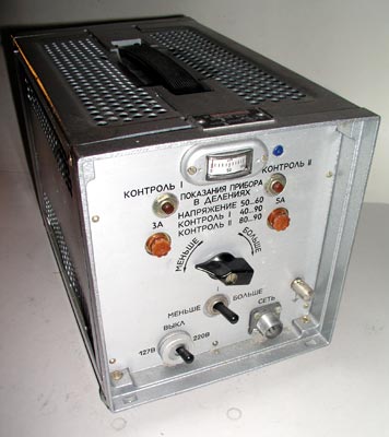
The front of the Fialka 24 volt DC power supply.
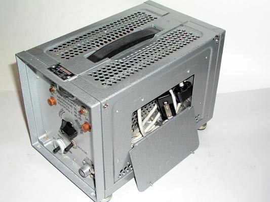
The right side of the Fialka 24 volt DC power supply showing the
compartment for storing the cables that connect the Fialka to the power
supply.
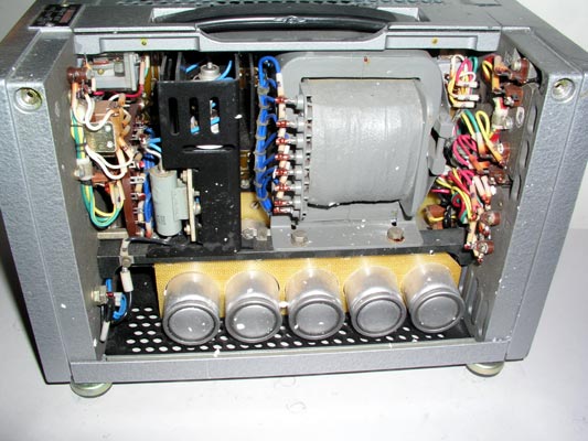
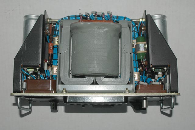
The right side of the Fialka 24 volt DC power supply after the cover is
removed. The power transformer and filter condensers are visible.
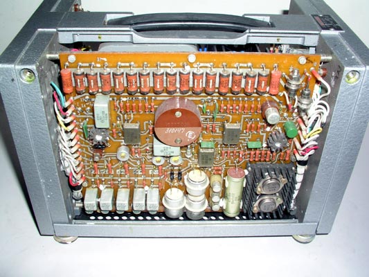
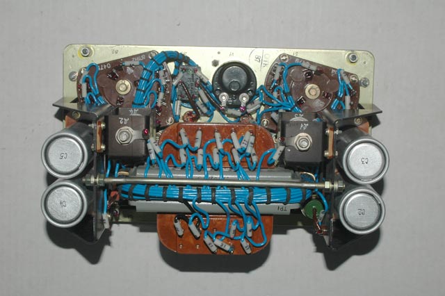
The left side of the Fialka 24 volt DC power supply after the cover is
removed. The voltage regulating circuitry is visible.
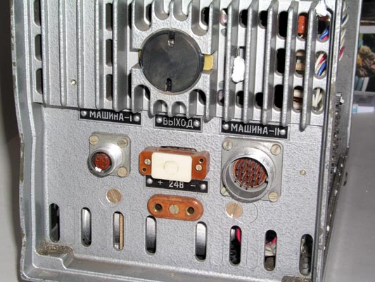
A close view of the back of the Fialka 24 volt DC power supply showing the
cable connectors.
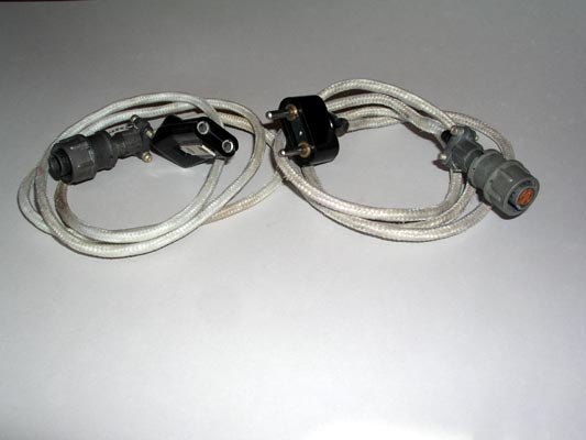
Two of the cables that connect the Fialka to its 24 volt power supply.
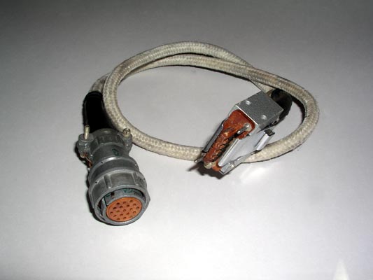
A third cable that connects the Fialka to its 24 volt power supply.
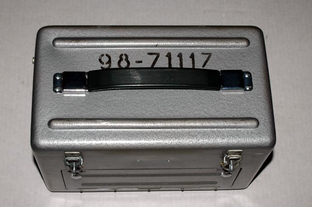
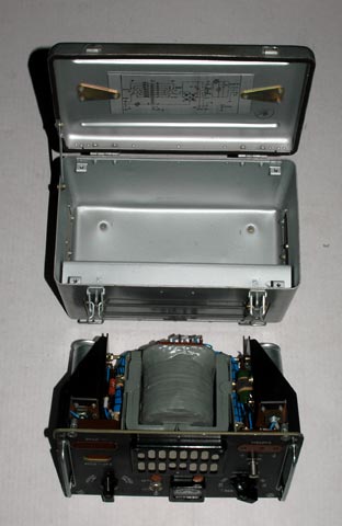
Top view of the power supply for the
M-125-3MN Fialka showing the cover closed.
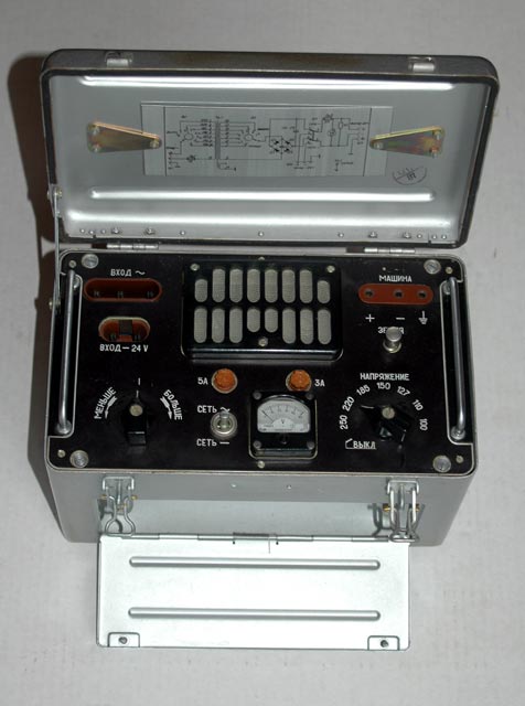
Top view of the power supply for the M-125-3MN Fialka showing the top cover
open. The door that covers the compartment where the power cables are stored
is shown in the open position. This power supply is used by both the M-125 and
the M-105 AGAT.
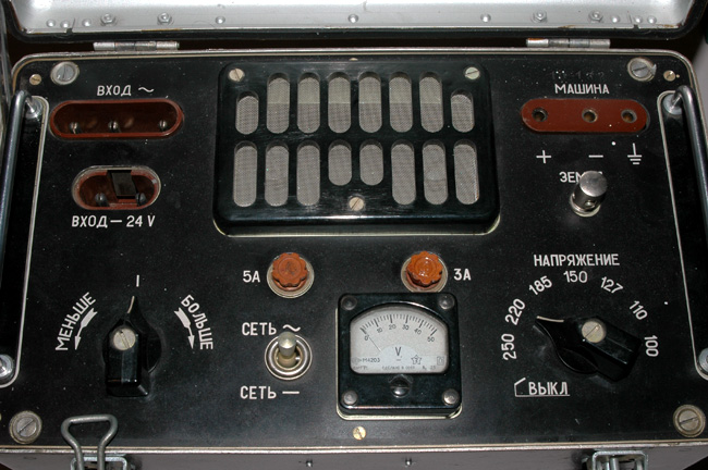
A closer view of the top of the power supply for the
M-125-3MN Fialka showing the controls and connectors.
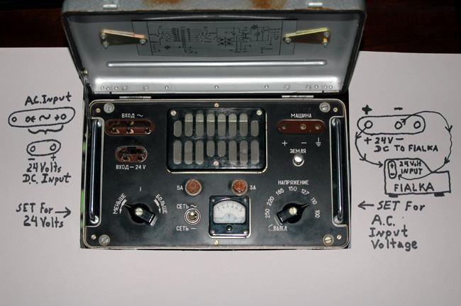
A view of the top of the power supply for the M-125-3MN Fialka showing the
controls and connectors and wiring for both AC and DC inputs.
Note that the AC goes into the top left connector and the switch in the
lower right sets the voltage to match the AC input. The switch in the lower
left adjusts the output voltage to exactly 24 Volts DC. If you supply DC to
the power supply, it goes into the lower left connector.
The output of the power supply goes to the Fialka as shown on the right.
Note that the two pins on the Fialka's connector receive +24 volts on the top
pin and -24 volts on the bottom pin. DO NOT REVERSE THIS WIRING ! +24 Volts
must go into the top pin on the Fialka.
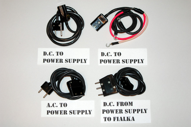
A very rare complete set of cables for supplying power to the
Fialka.
The cable for supplying 24 Volts DC to the power supply from a 24 Volt DC
power supply is on the top left.
The cable for supplying 24 Volts DC to the power supply from a battery is on
the top right.
The cable for supplying AC voltages to the power supply from a mains supply
is on the lower left.
The cable for supplying the 24 Volts from the power supply to the Fialka is
on the bottom right.
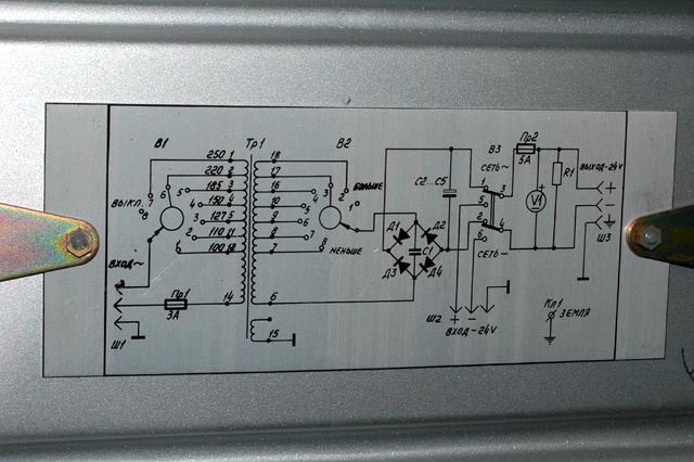
Top view of the power supply for the
M-125-3MN Fialka showing the circuit diagram
inside the cover.
Top view of the power supply for the
M-125-3MN Fialka with the circuitry removed
from the case.
The circuitry of the power supply for the
M-125-3MN Fialka.
The circuitry of the power supply for the
M-125-3MN Fialka.
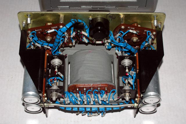
The circuitry of the power supply for the
M-125-3MN Fialka.
NOTE: I AM ALWAYS INTERESTED IN PHOTOGRAPHING OR BUYING VERY UNUSUAL ENIGMA-RELATED MATERIALS, PARTS, EARLY COMPUTERS, AND TELEGRAPH KEYS !
Professor Thomas B. Perera
Montclair State University
COPYRIGHT NOTICE: (Copyright (c) 2005: Prof. Tom Perera Ph. D.)
Although all the pictures and text are copyrighted, you may use any of them
for your own personal applications including public lectures and
demonstrations, publications and websites as long as you mention the
www.w1tp.com/enigma Museum. If you plan to offer them for sale to the public
in any form, you must email me for permission which I will generally grant as
long as you mention my museum: http://w1tp.com/enigma. My email address is
given at the bottom of this page. Some of the material may require contacting
other copyright owners for commercial use and I will inform you by email.
Please also see the disclaimer of warranty.