I have also produced a detailed set of photographs and descriptions of the
construction of the two different Fialka rotor sets. You may view them here:
Photographs, descriptions, wiring diagrams and advancing pin
data for Fialka rotors.
In addition, John Alexander located a German language manual for both models
of the Fialka and I have digitized the manual.
The German Language Fialka Manual clarifies
many aspects of the machine's operation and even shows one of the programming
cards that slide into the left side of the machine. If you have Adobe Acrobat
in your computer, you may want to view the German
Language Fialka Manual as an Adobe .pdf file (3.1MB)
Two versions of the Fialka have been identified and this manual applies to
both the M-125-3MN and M-125-MN Fialkas. The main differences between these
two machines are that the -3MN version has a very different keyboard, an
unique lever on the back of the case, switches alongside the keyboard, under
the base, and under the card reader matrix, a rotor rotation disconnect lever,
and the three bundles of wires coming from the reflector of the -3MN model in
contrast to the single bundle of wires coming from the -MN reflector. Both
models will be displayed and described below:
The Fialka is generally similar in design to the German Enigma cipher machine
but it has 10 rotors with 30 Russian characters/contacts instead of the 3 or 4
rotors with 26 letters/numbers/contacts in the German WW-2 Enigmas. The first
version of the Fialka, the M-100 was produced in the 1930s and it was followed
by the M-105 and then these M-125-MN and M-125-3MN models. The codename
"Fialka" is the Russian word for "Violet".
Instead of illuminating light bulbs to display the ciphertext resulting from
inputting plaintext into the keyboard, the Fialka prints the ciphertext on
paper tape and simultaneously punches holes in the tape in 5 level characters
resembling those of a Baudot teletype machine tape. The Fialka also includes
a paper tape reader for use in rapidly deciphering ciphertext punched into the
paper tape. Other important differences between the Fialka and the Enigma
include alternately counter-rotating rotors, wires coming from the reflectors,
and a switch to change the input wheel wiring.
There are two different sets of 10 rotors that can be inserted into either
model of the Fialka. The additional set of rotors is carried in a cylinder
inside the metal cover. One set is non-adjustable with fixed ring settings
and a fixed wiring maze. The other set is exceptionally cleverly designed in
that it allows for both the normal Enigma-like changes in ring settings
coupled with the ability to actually remove the internal wiring maze module
from each rotor. Once the wiring maze is removed, it may be reinserted into
the rotor in any of the 30 possible positions and/or flipped upside down and
inserted in any of the 30 positions. In addition, the wiring maze module
itself may be removed from the rotor and inserted into a different rotor.
This detailed rotor information can be seen here:
You will find a number of photographs showing various external and internal
views of the Fialka below. However, I think it is important to clarify various
aspects of the Fialka'a operation here. I will assume that you are familiar
with the operation of the German Enigma cipher machine and focus on the
differences between the Fialka and the Enigma.
Differences Between the Fialka and Other Cipher Machines:
Paper Tape:
One of the major differences is that the Fialka prints and punches its output
on 5-level paper tape. This punched paper tape can be read by eye, read into
a radioteletype transmitter, or read into another Fialka machine via its
internal tape reader. The Enigma and NEMA cipher machines used light bulbs to
illuminate letters that had to be written down by hand and then manually sent
and received by Morse code or manually typed into another cipher machine.
Card Reader:
Another difference is that the Fialka incorporates a card reader which allows
punched paper cards to be used to set internal coding parameters. These cards
replaced the clumsy, difficult to set, and therefore error prone plugboards of
the German Enigmas.
Rotor Rotation Direction:
Another difference is that the Fialka rotates each of its 10 rotors in a
direction that is opposite to that of each neighboring rotor. Other cipher
machines have rotors that all turn in the same direction. The pins that
control the rotation of individual rotors are described and the locations of
all pins for all rotors is given in a table in
this link.
Unique Rotors:
Another difference is that the Fialka can use both a simple, non-adjustable
set of rotors or an extremely unique and complex set of multi-adjustable
modular-wiring-matrix rotors that allow a very large number of internal wiring
variations. The rotors in the non-adjustable set are very simple. Each of
these rotors has a fixed wiring maze connecting the 30 input connections to
the 30 output connections. The other 10-rotor set consists of multi-
adjustable modular-wiring-maze rotors. Each rotor in this set has both an
adjustable external ring setting with 30 possible positions and a modular
wiring matrix that can be removed and reinserted in 60 different orientations
or inserted into another rotor body. This modular wiring matrix allows
the rotors to have a total of 60 unique and different internal wiring
layouts. All photographs and wiring data are given in
this link.
Unique Reflectors:
The reflector at the left end of the rotor stack is different from the
reflector in an Enigma and different in each Fialka model. In the M-125-MN,
the reflector has a single bundle of wires extending down from it. In the M-
125-3MN, the reflector has three bundles of wires coming out of it. It is
thought that these wires may be part of a circuit that allows the Fialka to
represent more Cyrillic letters than just the 30 represented by the 30 rotor
contacts and keyboard keys.
Unique Input Wheels:
The input wheel on the right end of the German Enigma rotor stack carries
voltages into and out of the rotor stack. It is non-adjustable. The Fialka
input wheel has two levers. One actually changes the internal wiring of the
input wheel, and, in the -3MN model, it also can totally disengage the rotor
drive mechanism. The second input wheel lever controls the paper tape punch.
How the 30 key keyboard may have been used to represent
33 Cyrillic letters:
In order to allow the use of the 30 key keyboard and 30 contact rotors, the
Russians probably did not use three letters from the 33 letter alphabet. They
probably omitted The soft E, usually shown as an E with an umlaut, the
reversed letter E which is actually a Greek letter with a short sound that is
often found in cognates, and the hard sign which has generally not been used
since the revolution.
Numbers were apparently represented by the 2, 5, 7, and 8 on the keyboard keys
and by other symbols. The Roman numeral 1 or I may have represented 1. The
Cyrillic 3 and soft sign may have represented 3 and 6 respectively. The
Cyrillic "ya" may have represented 9 with 10 being represented by the Cyrillic
"yu".
The following section describes and displays the Model M-125-MN Fialka. This
section is followed by, or linked to descriptions and photographs of the Model
M-125-3MN Fialka, the 24 Volt DC power supply and its cables and the metal
cover and accessories including a different rotor set.
Differences between the Model M-125-MN and Model M-125-3MN Fialkas:
The model M-125-MN does not include the following features that are
to be found in the model M-125-3MN described in another section.
These features are:
1. A multilingual keyboard.
2. A mechanical switch along the right side of the keyboard
that modifies keyboard function.
3. A 3-position lever on the back of the Fialka that modifies paper tape
punch operation.
4. A large matrix switch that alters the wiring of the programming matrix and
therefore the effect of the programming cards.
5. A rotary switch located under the base of the Fialka.
6. A position on the input rotor switch that stops rotation of the rotors and
character counting as characters are typed in.
7. An extended copyholder.
These features are described in detail in the section covering the
model M-125-3MN.
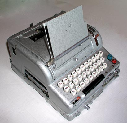
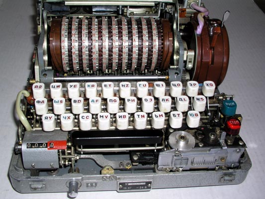
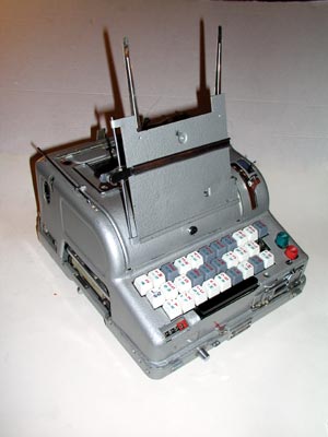
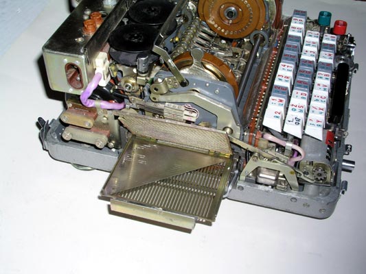
External Appearance and Features: Model M-125-MN
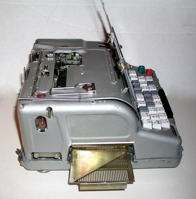
Left side view of the model M-125-MN Fialka showing the copy holder, the
letter counter and the slot for inserting the paper programming card.
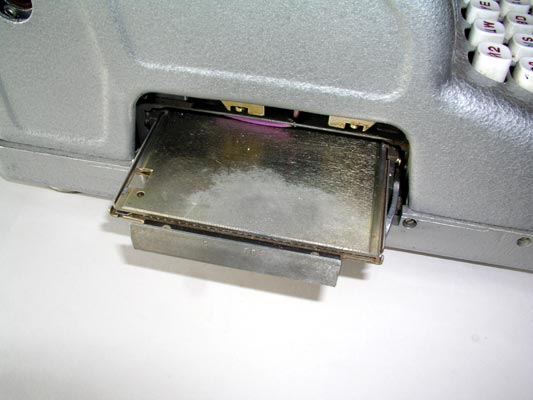
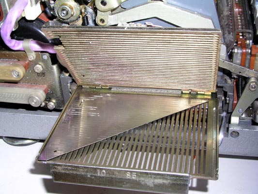
Closer view of the carrier for the paper programming card being pulled out.
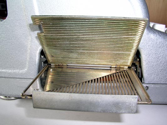
Closer view of the carrier for the paper programming card fully open to
allow insertion of the card.

Much closer view of the carrier for the paper programming card showing
the contacts that read the holes in the cards.
The Right side of the Fialka showing the copy holder, the switches on the
input wheel, the switch under the rotors, and the hole for the hand
crank that allows manual operation of the Fialka.
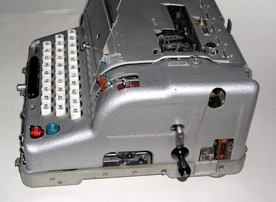
The Right side of the Fialka showing the hand crank that allows manual
operation of the Fialka and the switch located under the rotors.
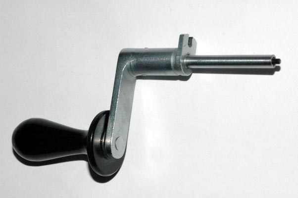
The hand crank that allows manual operation of the Fialka.
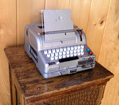
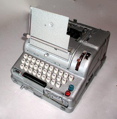
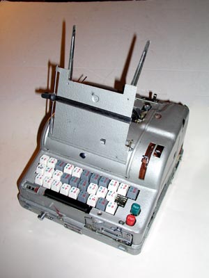
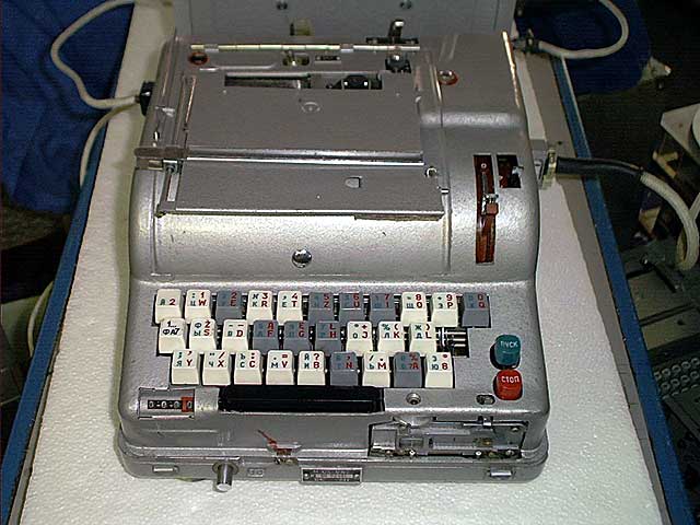
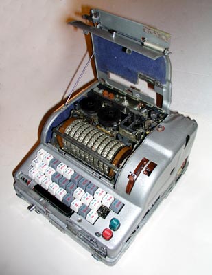
The Fialka resting on a wooden pedestal.
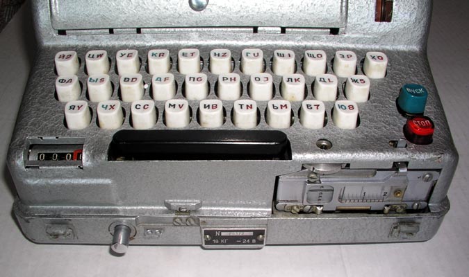
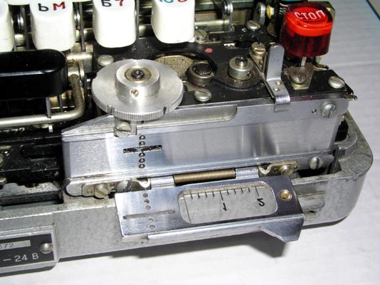
A closer view of the keyboard, the paper tape reader, and the character
counter. The reset button for the counter is located under the counter
between the counter and the space bar.
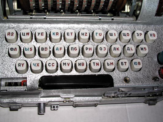
A Much closer view of the Russian keyboard.
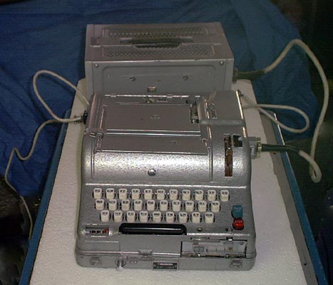
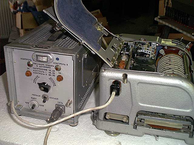
The Fialka connected to its 24 volt DC power supply.
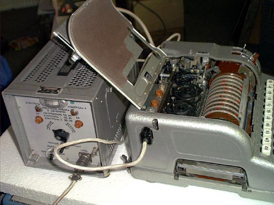
Left side of the Fialka connected to its 24 volt DC power supply.
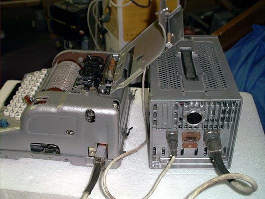
Right side of the Fialka connected to its 24 volt DC power supply.
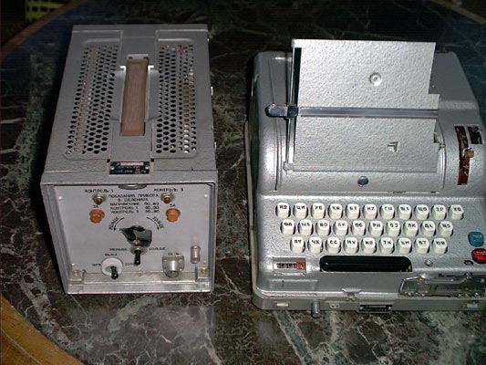
The Fialka and its 24 volt DC power supply.
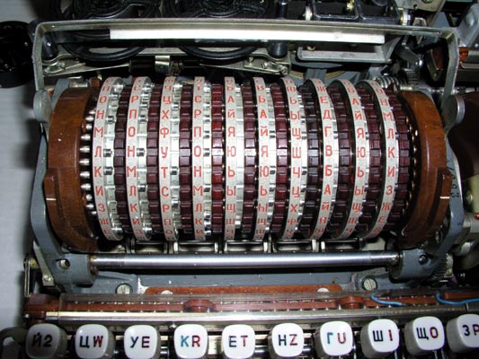
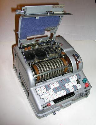
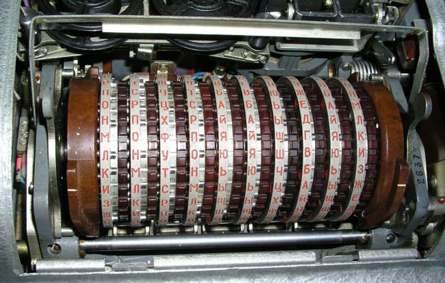
The 10 rotors after the cover door is opened. The index bar is raised
to the open position to allow the removal of the rotors.
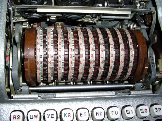
A closer view of the 10 rotors after the cover door is opened. The
index bar is raised to allow removal of the rotors.
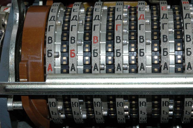
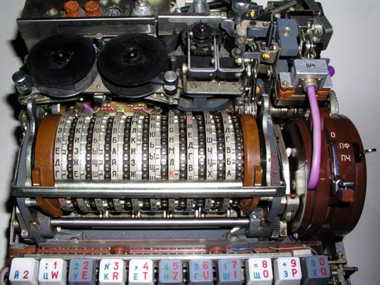
A close view of the 10 rotors with the index bar lowered and clicked into
position to aid in the accurate setting of the rotor positions. All rotors
have been set to the "A" position.
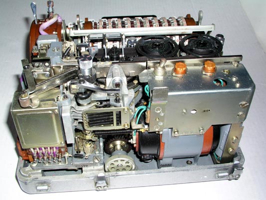
Appearance and Features of the Fialka seen with cover removed:
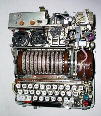
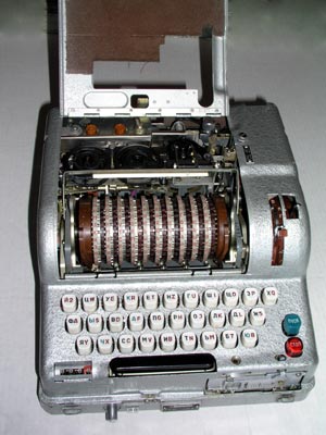
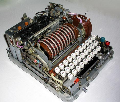
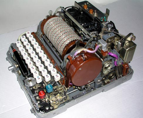
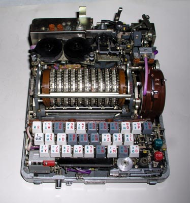
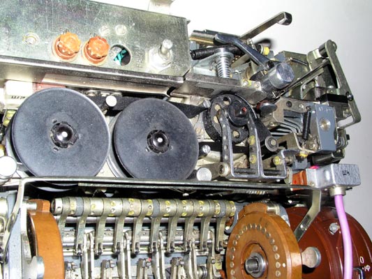
A top view of the Fialka with cover removed (3 screws). The power switch
and fuses are seen in the left rear. The paper tape printer ribbon reels,
printer, and paper tape punch are behind the 10 rotors. The brown reflector
is on the left end of the rotor stack. The adjustable input wheel is on the
right end of the rotor stack. The keyboard and manual paper tape feed wheel
are in front.
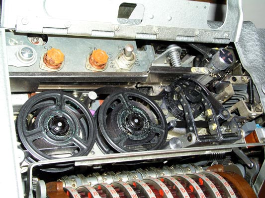
A closer view of the power switch, fuses, the paper tape printer ribbon
spools, the printer, and the punch mechanism.
A closer view of the paper tape reader mounted on the front of the Fialka.
Left side view of the Fialka with the cover removed showing the programming
card slot under the rotors and the reflector.
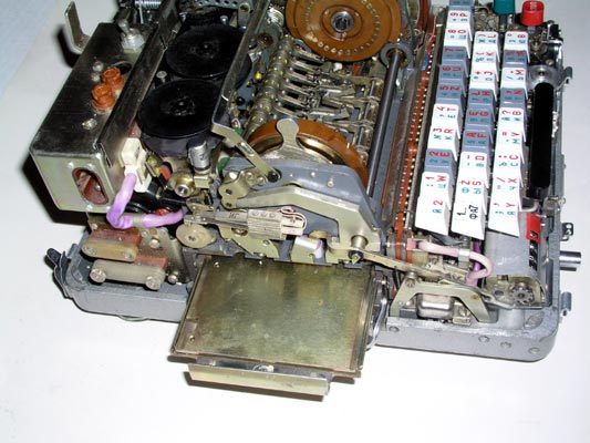
Front view of the Fialka showing the 10 rotors, the keyboard, the counter,
and the paper tape reader with the round paper tape advance wheel.
A closer view of the 10 rotors with the index bar raised to permit removal
of the rotor stack. The rounded metal handles on the two levers that push the
reflector on the left and the input wheel on the right inward have been moved
forward so that the reflector and input wheel may be pushed outwards to allow
the rotor stack to be removed. The brown color of the rotors indicates that
they are the Non-Adjustable rotors. The black multi-adjustable rotors are
described later under accessories and in the special detailed section on
rotors and rotor movement.
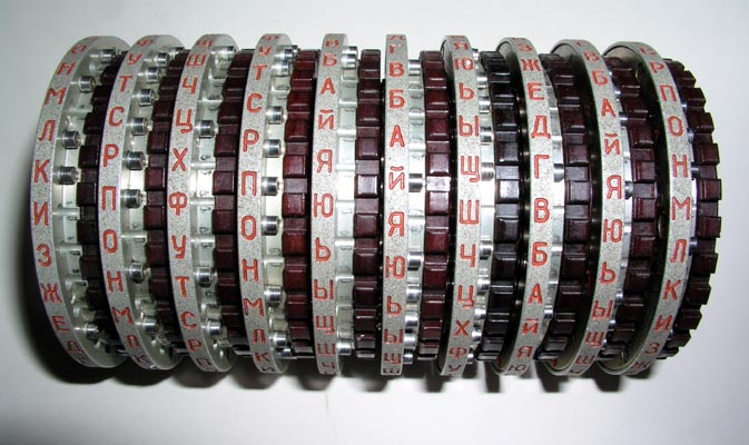
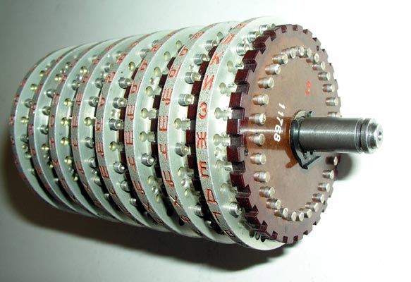
The 10 rotor stack of brown, Non-adjustable rotors is shown here after
removal from the Fialka.
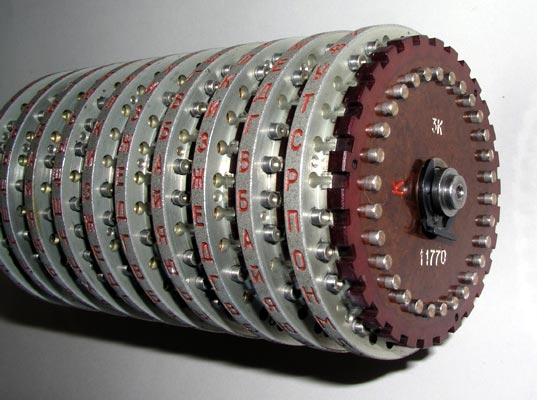
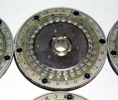
The 10 rotor stack showing the 30 spring loaded input contacts and the
retaining clip that keeps the rotors on the shaft.
The 10 rotor stack with the retaining clip removed and rotor "K" slid
off the shaft.

The 10 rotor stack with all but rotor "A" removed from the shaft.

The input contact sides of all 10 non-adjustable rotors after removal from
the shaft.
The output contact side of a non-adjustable rotor on the shaft.
The internal hand-wired set of connections between the input contacts and
the output contacts is called a wiring maze. It can be inspected or repaired
by removing a metal disc as shown here. The wiring maze of one of these
non-adjustable rotors is not designed to be changed.
The output contact sides of all 10 non-adjustable rotors after removal from
the shaft.
The shaft with the retaining clip in place to allow 8 rotors to be used
instead of 10. A special filler with contacts on both sides is used to fill
in the remaining space.
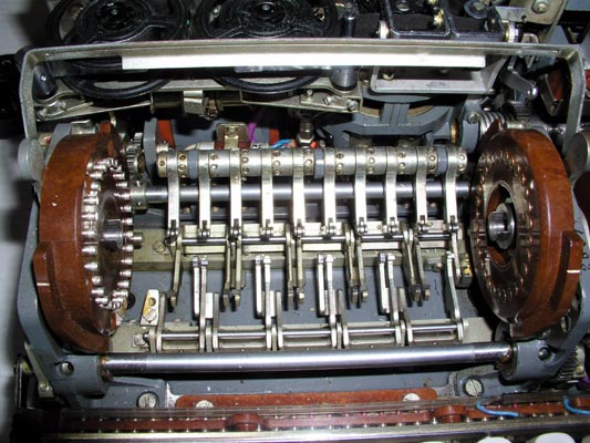
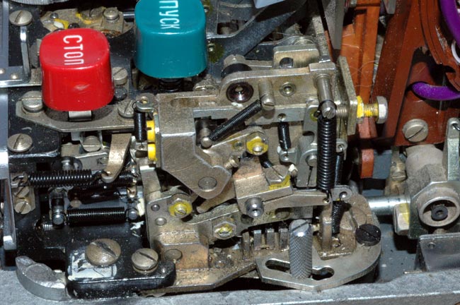
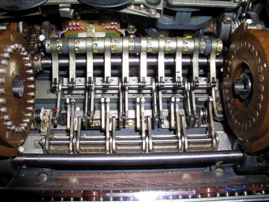
The drive mechanisms that produce the rotation of alternate rotors.
The lower horizontal bar activates cogs that pull forward on the bottoms of
rotors 2, 4, 6, 8 and 10 (counting from left to right) and rotate them so that
the tops of the rotors move AWAY from the keyboard.
The upper horizontal bar activates cogs that pull back on the bottoms of
rotors 1, 3, 5, 7 and 9 (counting from left to right) and rotate them so that
the tops of the rotors move TOWARD the keyboard.
A set of spring-loaded roller-equipped arms lock all 10 rotors into their
detent positions.
Highly detailed photographs and explanations of the rotation of the rotors are
given in this special rotor page:
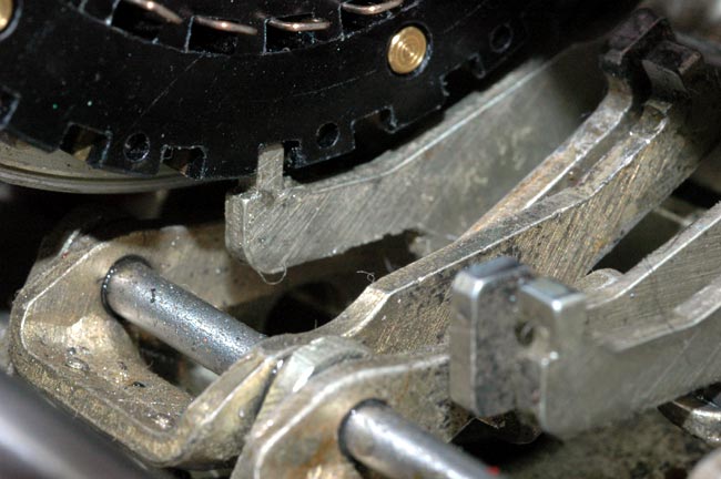
A very close view of one of the cogs that move toward the back of the
Fialka causing the rotor to rotate its top TOWARD the keyboard.
The cog mechanism and the advance blocking feeler for the second rotor to the
right of this one are also visible in the foreground. A much more detailed description, photographs, and tables explain the
rotation of the rotors in this link:
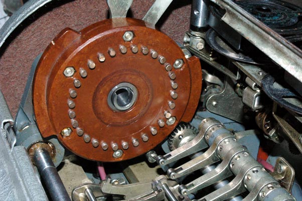
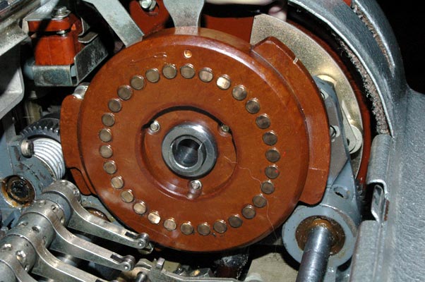
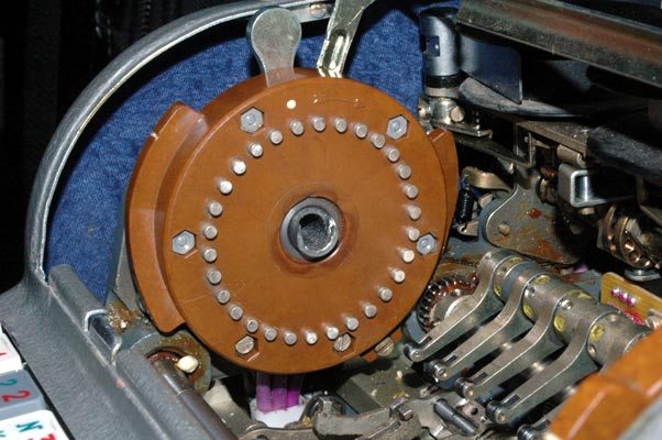
The reflector located on the left end of the rotor stack. Notice the
siingle bundle of wires coming down out of the reflector. It is thought that
these wires are part of a circuit that allows the Fialka to represent more
Cyrillic letters than just the 30 activated by the 30 rotor contacts.
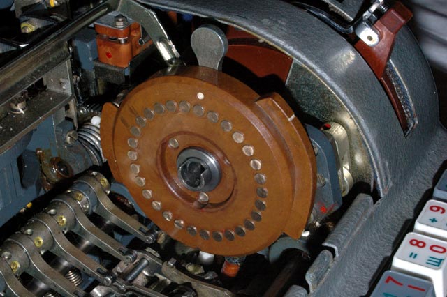
The input wheel located on the right end of the rotor stack. The input
wheel is connected to the complex switching system seen in the following
photographs.
The right side of the Fialka showing the input wheel and associated lever
and switch described in detail in the following photograph captions.
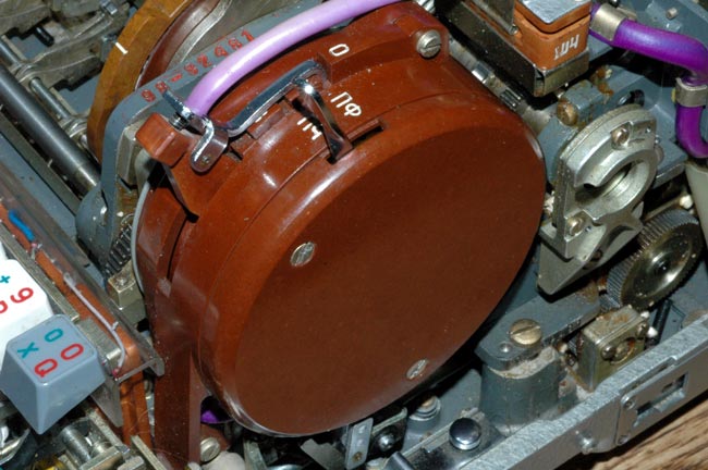
A closer view of the input wheel and switch assembly shows the 3 position
switch lever on the left and the paper tape punch control lever on the right.

Removing the cover of the input wheel switch assembly shows the internal
circuitry and paper tape punch control lever mechanism.

Removing the paper tape punch control lever from the input wheel switch
assembly shows the internal circuitry more clearly.
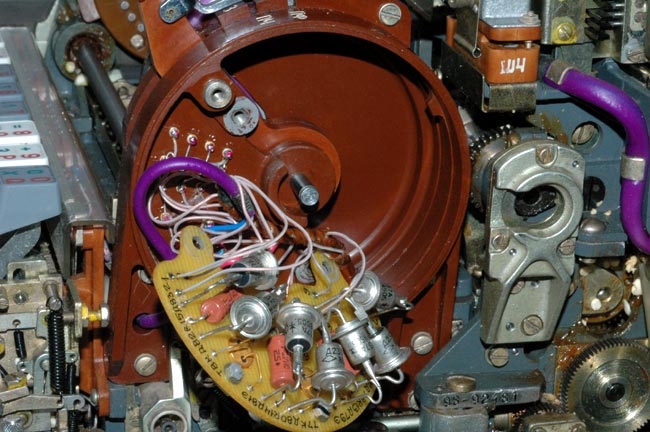
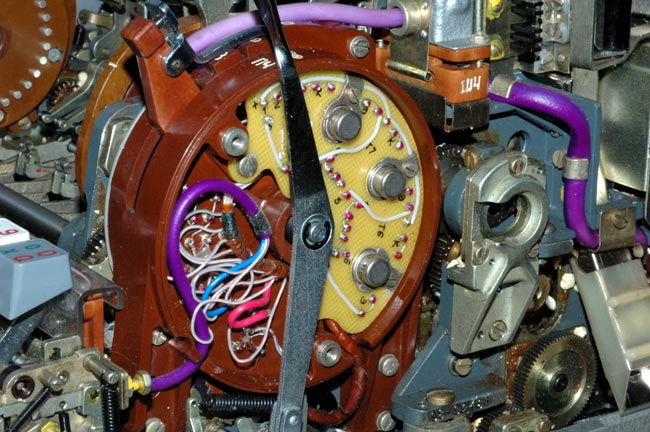
Pulling the circuit board outwards reveals the 7 power diodes and
other components.

Pulling the circuit board farther out of the way reveals the switching
mechanism that is activated by the lower two positions of the 3 position
input wheel switch. The uppermost position of the switch lever does nothing
in the M-125-MN Fialka but completely disables rotor rotation and character
counter activation in the M-125-3MN Fialka.
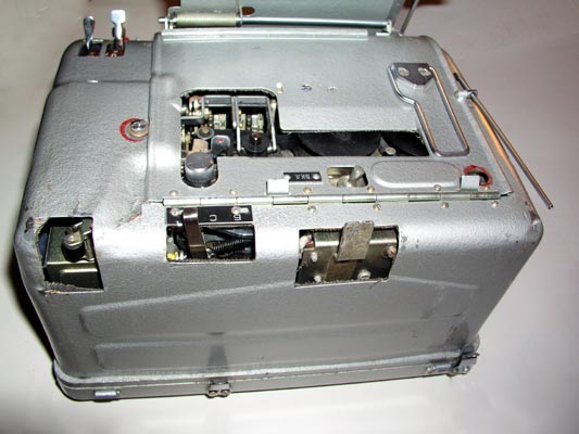
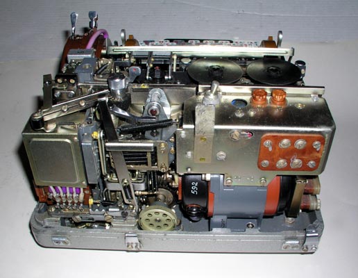
The back of the Fialka with the cover removed showing the drive motor. The
metal box at the left contains the 5 paper tape punch operating solenoids
shown in the next photograph.

The 5 paper tape punch operating solenoids are located under a metal cover
in the back right corner of the Fialka.
Detailed Rotor Wiring and Rotation Data, Photographs, and
Descriptions may be viewed at this link:
Descriptions of the Power Supply, Cables, Cover and Accessories including a
different rotor set will be found after the description of the model M-125-
3MN Fialka.
The following section describes and displays the Model M-125-3MN Fialka.
This section is followed by, or linked to descriptions and photographs of the
Model M-125-MN Fialka, the 24 Volt DC power supply and its cables and the
metal cover and accessories including a different rotor set.
The model M-125-3MN Fialka is much more complex than the M-125-MN version with a number of major differences:
Differences between the Model M-125-MN and Model M-125-3MN Fialkas:
The M-125-3MN has many complex features that are not included in the M-125-MN.
These include:
1. A multilingual keyboard.
2. A mechanical switch along the right side of the keyboard
that modifies keyboard function.
3. A 3-position lever on the back of the Fialka that modifies paper tape
punch operation.
4. A large matrix switch that alters the wiring of the programming matrix and
therefore the effect of the programming cards.
5. A rotary switch located under the base of the Fialka.
6. A position on the input rotor switch that stops rotation of the rotors and
character counting as characters are typed in.
7. An extended copyholder.
All of these features will be shown and described in the following page:
Descriptions, Photographs, and Partial Disassembly of the
M-125-3MN Fialka:
Note: The pictures show a model M-125-3Mp2 Fialka which is very similar to a
model M-125-3MN.
External Appearance and Features:
The left side view of the M-125-3MN Fialka shows the copy holder with its
extensions, the character counter and the slot for the paper programming card.
The carrier for the paper programming card being pulled out of the left side
of the Fialka to allow insertion of the card.
Closer view of the carrier for the paper programming card opening to allow
insertion of the card.
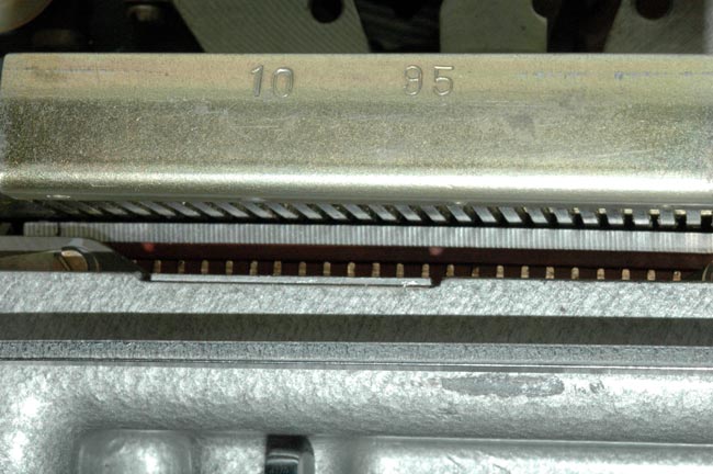
Closer view of the contacts that are activated by the programming card.
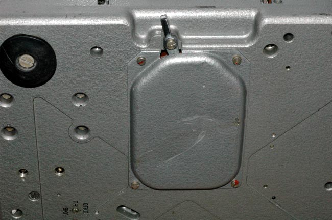
The underside of the M-125-3MN showing the unique chromed programming card
matrix switch lever that changes all of the contacts in the card reader. This
switch is not found in the M-125-MN model.
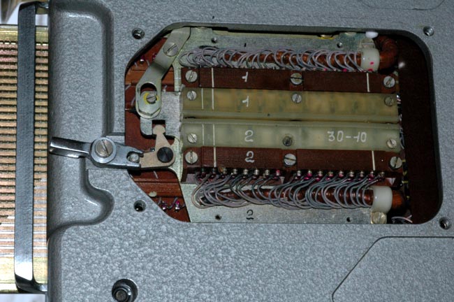
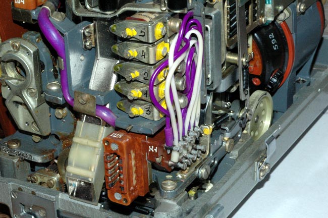
Removing the cover over the switch reveals the complicated mechanism. The
lever moves the white plastic central contacts to the right when it is
activated as shown in the next photograph. This switch is not found in the M-
125-MN model.
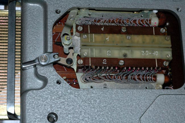
In this photo the lever has moved the white plastic central contacts to the
right thus changing the entire wiring of the programming card reader matrix.
This switch is not found in the M-125-MN model.
Another unique feature of the M-125-3MN model is this rotary switch that is
located near the center of the bottom of the base of the Fialka. This switch
is not found in the M-125-MN model.
The Right side of the Fialka showing the copy holder and input wheel
levers. The switch under the rotors, and the hole for the hand crank
that allows manual operation of the Fialka are just barely visible.
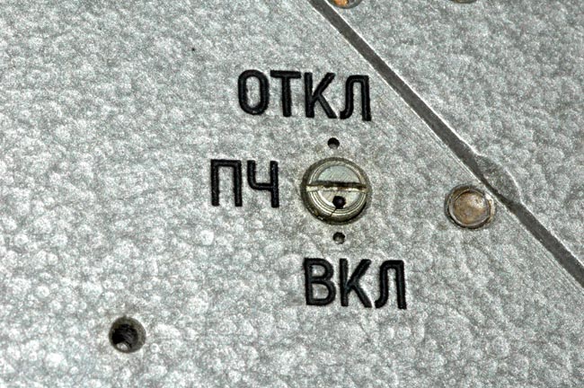
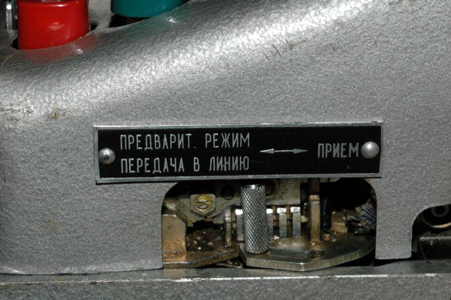
The switch (left) and paper tape control lever (right) on the input wheel
switch assembly that is located on the right side of the Fialka. In this
M-125-3MN model, the switch in the 0 position as shown disables rotation of
the rotors and incrementing of the character counter. In the M-125-MN model,
this position of the switch has no effect.
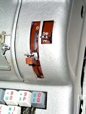
The Rear of the Fialka showing the three position lever that is not found
on the M-125.MN model. It is located half way between the center and the left
corner. The lever must be pushed downwards to unlock it and allow it to be
set to one of the three positions.

A front view of the Fialka showing the keyboard with the paper tape reader
on the right and the character counter on the left.
This mechanical switch located under the right side of the keyboard
modifies the function of the keyboard. This switch is not found on the
Model M-125-MN Fialka.
This picture shows the mechanical switch under the right side of the
keyboard with the cover removed. The knurled and slotted activating pin is
positioned between the left and right positions. It modifies the function of
the keyboard. This switch is not found on the Model M-125-MN Fialka.
The Fialka connected to its 24 volt DC power supply.
The left side of the Fialka connected to its 24 volt DC power supply.
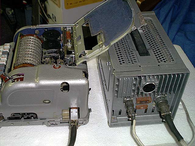
The right side of the Fialka connected to its 24 volt DC power supply.
The 10 rotors after the cover door is opened. The index bar is lowered in
place in front of the rotors to allow accurate setting.
Another view of the 10 rotors after the cover door is opened. The index
bar is lowered in place in front of the rotors to allow accurate setting.
Appearance and Features of the Fialka seen with cover removed:
A top view of the Fialka with cover removed (3 screws). The power switch
and fuses are in the left rear. The paper tape printer ribbon reels, the
printer and the paper tape punch are behind the 10 rotors. The brown reflector
is on the left end of the rotor stack. The adjustable input wheel is on the
right end of the rotor stack. The keyboard and paper tape reader with its
manual paper tape feed wheel are in front.
A closer view of the power switch, fuses, the paper tape printer ribbon
spools, the printer, and the punch mechanism. The unique 3 position lever is
seen extending upwards from the rear of the mechanism.
A view of the back of the Fialka after removal of the cover. Note the
3-position lever to the left of the center of the machine. It appears to
modify the functioning of the paper tape punch mechanism. This lever is not
found on the model M-125-MN Fialka.
Note the metal box on the left corner of the mechanism. It houses the
paper tape punch solenoids as shown in the next photograph.
The 5 paper tape punch operating solenoids are located under a metal cover
in the back right corner of the Fialka. Note also the 3-position switch lever
with the three detent positions located in back of and below the colored
wires. It is located in front of the manual mechanism drive wheel with its
arrow indicating the correct direction of rotation.
The left side view of the Fialka with the cover removed showing the programming
card holder under the rotors and the reflector.
Another left side view of the Fialka with the cover removed showing the
programming card holder pulled all the way out and opened to accept a
programming card.
A close view of the programming card holder pulled all the way out and
opened to accept a programming card.
Front view of the Fialka showing the 10 rotors with the index bar in place
to facilitate setting the rotor positions accurately.
A closer view of the 10 rotors with the index bar raised to permit removal
of the rotor stack.
The two rounded levers that push the reflector on the left and the input wheel
on the right inward have been pulled forward so that the reflector and input
wheel may be pushed outwards to allow the rotor stack to be removed.
The brown color of the rotors indicates that they are the Non-Adjustable
rotors. The black multi-adjustable rotors are described later under
accessories and in the special detailed section on rotors and rotor
movement.
The 10 rotor stack of brown, Non-adjustable rotors is shown here after
removal from the Fialka.
The input contact sides of one of the 10 non-adjustable rotors after
removal from the rotor shaft. Note the grease which lubricates the rotor and
improves contact reliability.
The output contact side of one of the 10 non-adjustable rotors after
removal from the rotor shaft.

The internal hand-wired set of connections between the input contacts and
the output contacts is called a wiring maze. It can be inspected or repaired
by removing a metal disc as shown here. The wiring of these non-adjustable
rotors is not designed to be changed.
NOTE: Please refer to the description of the M-125-MN Fialka (above)
for a more complete set of photographs and descriptions of these brown non-
adjustable rotors. The black multi-adjustable rotors are described in detail
in the section on accessories at the bottom of this page.
The drive mechanisms that produce the rotation of alternate rotors.
The lower horizontal bar activates cogs that pull forward on the bottoms of
rotors 2, 4, 6, 8 and 10 (counting from left to right) and rotate them so that
the tops of the rotors move AWAY from the keyboard.
The upper horizontal bar activates cogs that pull back on the bottoms of
rotors 1, 3, 5, 7 and 9 (counting from left to right) and rotate them so that
the tops of the rotors move TOWARD the keyboard.
A set of 10 spring-loaded arms with rollers holds the 10 rotors in their
detent positions.
Highly detailed photographs and explanations of the rotation of the rotors are
given in this special rotor page.

A very close view of one of the cogs that move toward the back of the
Fialka causing the rotor to rotate its top TOWARD the keyboard.
The cog mechanism and the advance blocking feeler for the second rotor to the
right of this one are also visible in the foreground. Much
more detailed descriptions, photographs, and tables explain the rotation of
the rotors in this link:
The reflector located on the left end of the rotor stack. Notice the three
bundles of wires coming down out of the reflector. The Model M-125-MN has
only a single bundle of wires exiting the reflector. It is thought that these
wires may be part of a circuit that allows the Fialka to represent more
Cyrillic letters than just the 30 represented by the 30 rotor contacts and
keyboard keys.
The input wheel located on the right end of the rotor stack. The input
wheel is connected to the complex switching system seen in the following
photographs.

A closer view of the input wheel and switch assembly shows the 3 position
switch lever on the left and the paper tape control lever on the right. Notice
that the 3-position switch is in the uppermost position. In this position, it
disables rotation of the rotors and incrementing of the character counter. It
does not have any function in the top position in the M-125-MN Fialka.
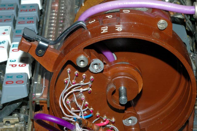
Removing the cover of the input wheel switch assembly shows the internal
circuitry and paper tape punch control lever mechanism.
Removing the paper tape punch control lever from the input wheel switch
assembly shows the internal circuitry more clearly.

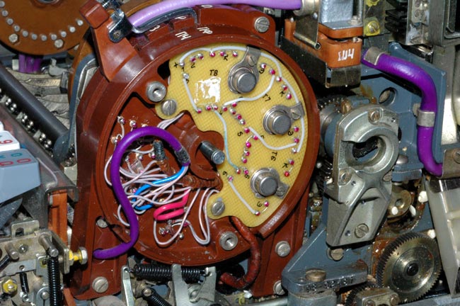
Pulling the circuit board outwards reveals the 7 power diodes and
other components.
Pulling the circuit board farther out of the way reveals the switching
mechanism that is activated by the lower two positions of the 3 position input
wheel switch.
The uppermost position ( "O" ) of the switch lever completely disables rotor
rotation and character counter activation in the M-125-3MN Fialka. It has no
effect at all on the functioning of the M-125-MN Fialka.
Differences Between the Fialka Rotors and Those of Other Cipher
Machines:
Rotor Rotation Direction:
One of the differences is that the Fialka rotates each of its 10 rotors in a
direction that is opposite to that of each neighboring rotor. Other cipher
machines have rotors that all turn in the same direction. The rotor advance
blocking pins that control the rotation of individual rotors are described and
the locations of all pins for all rotors are given in a table below.
Unique Rotors:
Another difference is that the Fialka can use both a simple, non-adjustable
set of rotors or an extremely unique and complex set of multi-adjustable
modular-wiring-matrix rotors that allow a very large number of internal wiring
variations. These simple and complex rotors are described in detail below and
their internal wiring data is presented in a comprehensive table.
Rotor Overview:
There are two different sets of 10-rotors that fit into the Fialka. The
rotors in one set are very simple and they are non-adjustable. Each rotor has
a fixed wiring maze connecting the 30 input connections to the 30 output
connections. This non-adjustable set will be described first below.
The other 10-rotor set consists of multi-adjustable rotors. Each rotor in this
set has both an adjustable external ring setting with 30 possible positions
and a modular wiring matrix that can be removed and reinserted in 60 different
orientations. This modular wiring matrix allows the rotors to have a total of
60 unique and different internal wiring layouts.
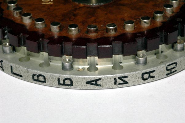
Input Contacts:
Each rotor has 30 contacts that are identified by 30 letters of the Cyrillic
Alphabet that are stamped around the outer ring of the rotor. The contacts
receive electrical voltages from the input wheel on the right side of the
Fialka and are therefore called the input contacts. These contacts are on the
RIGHT side of the rotors when they are inserted into the Fialka. The RIGHT
side of the rotors face the input wheel which on the far right side of the
Fialka and which carries the voltages from the keyboard to the rotor
stack.

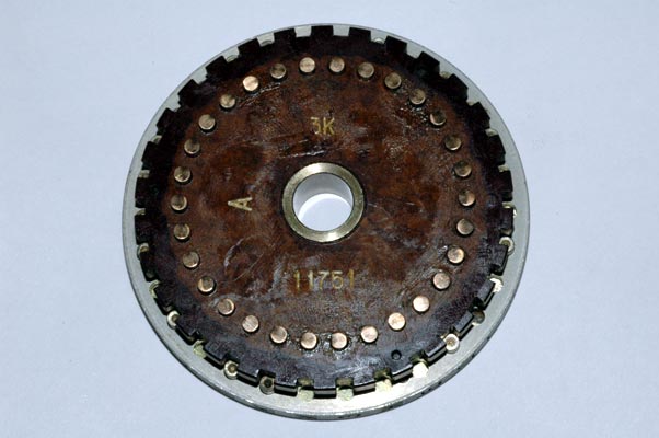
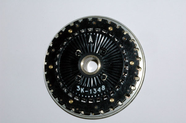
The Thirty Input Contacts for the Non-Adjustable Rotor "A". The heavy
lubricating grease lubricates the contacts and eases rotation.
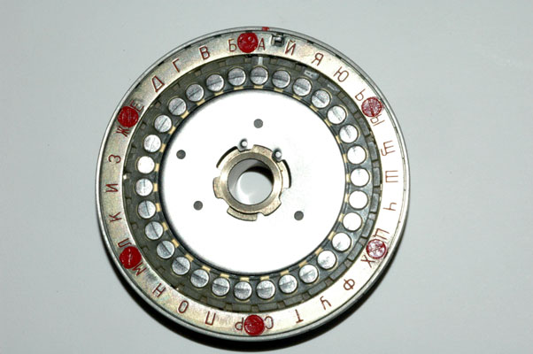
Output Contacts:
The other side of the rotor contains the 30 output contacts that pass the
electrical voltage out of the rotor and LEFT to the next rotor in the stack or
to the reflector at the far left. Each of these output contacts is identified
by a letter from the Russian Cyrillic Alphabet that is stamped on the outer
ring of the rotor.

The Thirty Output Contacts for the Non-Adjustable Rotor "A".

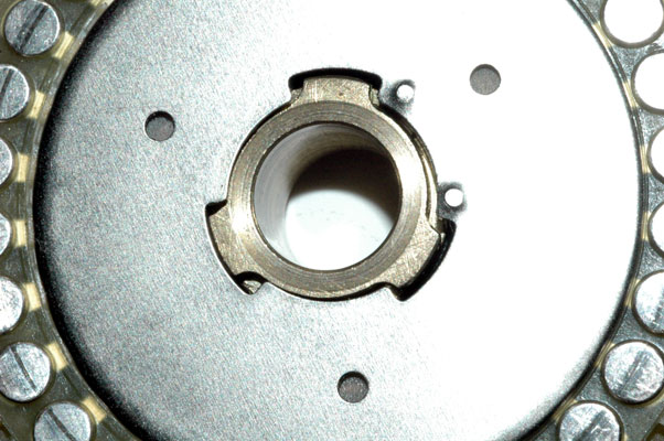
The non-adjustable rotors can be disassembled to allow access to the wiring
maze but no changes can be made to the maze. To access the wiring, this metal
disc is rotated until it releases the brass central shaft as shown in the next
photograph.
 The metal disc has been rotated until it releases the brass central shaft.
The metal disc and the insulating fiber washer have been moved aside to
reveal the hand-wired wiring maze. Access to the wiring maze makes it easier
to repair any cold-soldered joints.
The wiring maze is shown in this photograph.
Here is a closer view of the wiring maze.
Specific Wiring Data for all Non-Adjustable Rotors:
The 30 wired connections between the 30 input contacts and the 30 output
contacts are fixed and can not be changed. The Cyrillic letter stamped on
the outer ring and associated with each contact is also fixed and can not be
changed. The exact wiring between the 30 input and output connections is
given for each of the 10 rotors in a table below. This table shows the
Cyrillic and the corresponding numerical identifier for each of the 30 INPUT
contacts in a column on the left side of the table. The OUTPUT contact that
is fixed-wired to each of the input contacts is given by the number in the
table under the Cyrillic letter identifying each of the 10 rotors. To convert
this number back into its corresponding Cyrillic letter, just use the column
on the left.

**SPECIAL NOTE: The column on the far right side of the table shows the
output contacts that are connected to the 30 input contacts of MULTI-
ADJUSTABLE ROTOR "K" WHEN THE REMOVABLE MODULAR WIRING MAZE HAS BEEN REMOVED
AND REVERSED SO THAT SIDE "2" FACES OUTWARDS AND THE INDEX MARK POINTS TO THE
CYRILLIC LETTER "A". For a further description of this setting, please see
the information on the multi-adjustable rotors below:
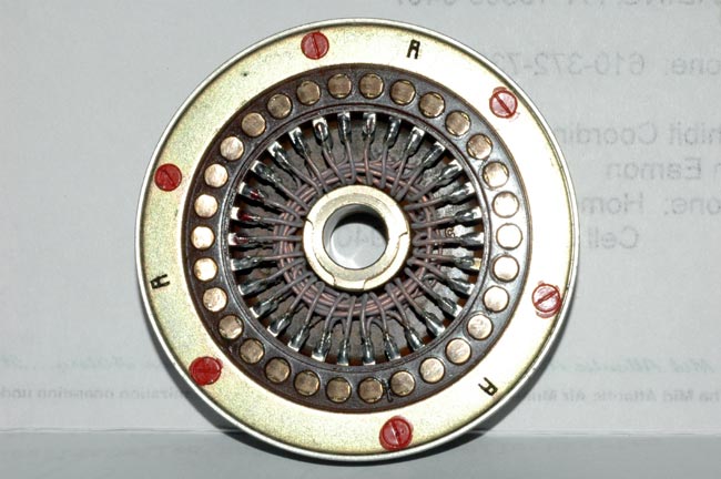
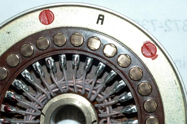
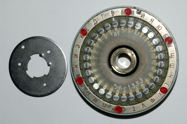
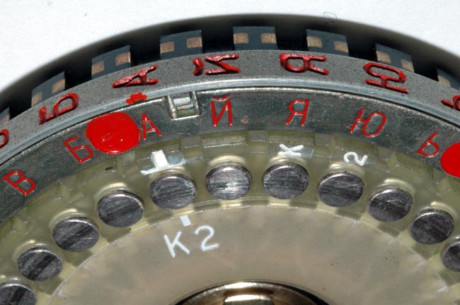
Rotor Rotation Advance Blocking Pins:
The actual rotation of the rotors is controlled by the placement of the metal
pins adjacent to each of the contacts. These pins block or lock-out the
drive mechanism and determine which rotors will not rotate. This photograph
shows several of the pins and several of the un-pinned locations. A detailed
table showing the locations of all of the pins in all of the rotors may be
found below.
Although all known Fialka rotors have exactly the same rotor advance blocking
pin placements it is possible, with a considerable amount of effort, to
change the placements. These pins can be removed from the rotors and inserted
into other holes but it is quite difficult to do this. It does not appear
to be a real adjustment of the rotor but rather an assembly convenience and
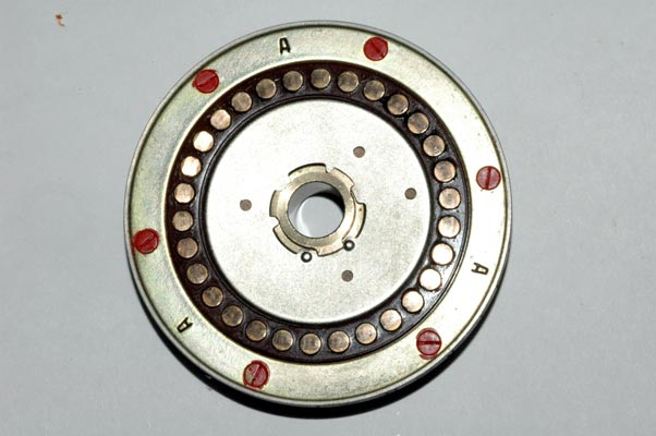
perhaps a provision for a major engineering revision. To remove the pins, the
6 screws holding the outer ring plate must be unscrewed. Each screw is
covered with red paint that both makes it difficult to unscrew, and also
reveals any attempts to do so. After the outer ring plate is removed, the
pins drop out of their cylindrical holes and can be repositioned. This is so
difficult and complex that for field and operational use, it can safely be
assumed that these pins are always to be found in the positions shown in the
table.
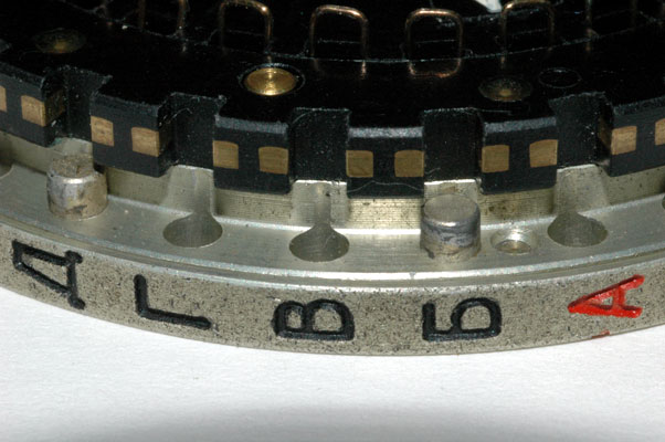
This is a close view of the rotation advance blocking pins
for one of the rotors:
Table showing and explaining the rotation advance blocking pin locations
for all 10 rotors:
This table gives the locations of the advance blocking pins for the Non-
Adjustable and Multi-Adjustable Fialka Rotors. These pins determine whether
the rotor will advance or not as each letter is typed in. These pins block
the advance of rotors by blocking specific advance cogs underneath the rotor
stack.
The advance blocking pins (marked with an "x" for each rotor in the table) are located at the position identified by the Cyrillic letter and contact number shown in the column on the left. EXAMPLE: For rotor "A" there is no rotor advance blocking pin in position 1 which is marked with the Cyrillic letter "A". There is, however, a blocking pin located at position 2.
Please note that this table only gives the actual physical location of the
advance blocking pins. The rotor advance sequence is as shown but the actual
point of advance is different from these locations. The actual position where
the cogs engage and drive the rotors is described below:
Please also note that the Non-Adjustable and Multi-Adjustable rotors are
identical ONLY when the multi-adjustable rotors are set to their overall
'BASE' setting. In the overall BASE setting, the outer lettered ring is set so
that the Cyrillic letter "A" is Adjacent to the Cyrillic letter "A" on the
main rotor frame. Then the internal modular wiring maze is removed and placed
back into the rotor so that its index mark points to the Cyrillic letter "A"
and so that its side "1" is facing outward. Please see the accompanying text
for an explanation of the special multi-adjustable modular-wiring-maze
rotors.
Rotors 2, 4, 6, 8 & 10 (reading from left-to-right)
The actual advancing of rotors 2, 4, 6, 8 & 10 is activated by a drive cog
that engages the rotor at position 18 (When the rotor is set to the "A"
position). An advance blocking pin in the rotor in this position (position
18) will block the rotation of any of these even-numbered rotors to the RIGHT
of that rotor. As the rotors rotate, the place that the advancing cog engages
the rotor changes accordingly.
Rotors 2, 4, 6, 8 & 10 Rotate their upper letters AWAY from the keyboard.
Their rotation is driven by rotor 2 which drives rotors 4, 6, 8 & 10 in that
order. For these 5 rotors, ANY Rotor Advance Blocking Pins existing in the
drive slot of a rotor to the LEFT of a given rotor will prevent it from
rotating. In other words, a Rotor Advance Blocking Pin blocks the rotation of
any of these 5 rotors to the RIGHT of the rotor that has the pin. Rotor
Advance Blocking Pin locations are given in an accompanying table.
Rotors 1, 3, 5, 7 & 9 (reading from left-to-right)
The actual advancing of rotors 1, 3, 5, 7 & 9 is activated by a drive cog that
engages the rotor at position 21 (When the rotor is set to the "A" position).
An advance blocking pin in the rotor in this position (position 21) will block
the rotation of any of these odd-numbered rotors to the LEFT of that rotor.
As the rotors rotate, the place that the advancing cog engages the rotor
changes accordingly.
Rotors 9, 7, 5, 3 & 1 Rotate their upper letters TOWARD the keyboard. Their
rotation is driven by rotor 9 which drives rotors 7, 5, 3 & 1 in that order.
For these 5 rotors, ANY Rotor Advance Blocking Pins existing in the drive slot
of a rotor to the RIGHT of a given rotor will prevent it from rotating. In
other words, a Rotor Advance Blocking Pin blocks the rotation of any of these
5 rotors to the LEFT of the rotor that has the pin. Rotor Advance Blocking
Pin locations are given in an accompanying table.

Sample Rotor Rotation Data:
Sample rotation data for all 10 rotors for the first 20 letters typed into the
Fialka are shown in a table below:
This table gives sample rotor advancing data for the first 20 letters typed
into a Fialka for all 10 rotors after the rotors have been set to starting
position: A A A A A A A A A A. This table applies to both the Non-Adjustable
and Multi-Adjustable rotors when the Multi-Adjustable rotors are set to their
BASE ring setting. (This BASE setting of the multi-adjustable rotors has all
Cyrillic letter "A"s on the outer ring set Adjacent to the Cyrillic letter
"A"s on the inner ring of the rotor). The table has been constructed in the
following way:
First, each of the 10 rotors was inserted into the Fialka as shown at the very
top of the table with rotor "A (1)" on the far left and rotor "K (10)" on the
far right. (The rotors have been given numbers for convenience in
understanding the paragraphs in the next section:)
Then All 10 rotors were manually rotated to position "A". (The state in which
all rotors are set to position "A" is shown in the table as 1, 1, 1, 1, 1, 1,
1, 1, 1, 1 in the top row of the table.
Finally, 20 letters were typed into the Fialka. Each letter caused some of
the rotors to rotate. The position that each of the 10 rotors had reached
after each letter was entered is shown in the table by a number that
corresponds to a Cyrillic Letter on the outer ring of the rotor.
These numbers may be converted into their Cyrillic letter equivalents by using
the column on the right side of the table which is just placed there as a
convenience in making the conversions.
Rotors 2, 4, 6, 8 & 10 (reading from left-to-right)
Rotors 2, 4, 6, 8 & 10 Rotate their upper letters AWAY from the keyboard.
Their rotation is driven by rotor 2 which drives rotors 4, 6, 8 & 10 in that
order. For these 5 rotors, ANY Rotor Advance Blocking Pins existing in the
drive slot of a rotor to the LEFT of a given rotor will prevent it from
rotating. In other words, a Rotor Advance Blocking Pin blocks the rotation of
any of these 5 rotors to the RIGHT of the rotor that has the pin. Rotor
Advance Blocking Pin locations are given in an accompanying table.
The actual advancing of rotors 2, 4, 6, 8 & 10 is activated by a drive cog
that engages the rotor at position 18 (When the rotor is set to the "A"
position). An advance blocking pin in the rotor in this position (position
18) will block the rotation of any of these even-numbered rotors to the RIGHT
of that rotor. As the rotors rotate, the place that the advancing cog engages
the rotor changes accordingly.
Rotors 1, 3, 5, 7 & 9 (reading from left-to-right)
Rotors 9, 7, 5, 3 & 1 Rotate their upper letters TOWARD the keyboard. Their
rotation is driven by rotor 9 which drives rotors 7, 5, 3 & 1 in that order.
For these 5 rotors, ANY Rotor Advance Blocking Pins existing in the drive slot
of a rotor to the RIGHT of a given rotor will prevent it from rotating. In
other words, a Rotor Advance Blocking Pin blocks the rotation of any of these
5 rotors to the LEFT of the rotor that has the pin. Rotor Advance Blocking
Pin locations are given in an accompanying table.
The actual advancing of rotors 1, 3, 5, 7 & 9 is activated by a drive cog that
engages the rotor at position 21 (When the rotor is set to the "A" position).
An advance blocking pin in the rotor in this position (position 21) will block
the rotation of any of these odd-numbered rotors to the LEFT of that rotor.
As the rotors rotate, the place that the advancing cog engages the rotor
changes accordingly.
Suppose you insert all Fialka rotors such that the rotors are in the order
shown at the top of the table.
Suppose you set all Fialka rotors to the letter "A" position.
Suppose you would like to predict the rotation of rotor 4 as you type in 5
letters.
1. Remember that the drive cog for rotors 2, 4, 6, 8 & 10 is located at
position 18 (Very Important).
2. Look at the table that shows the locations of the rotor advance blocking
pins.
3. Note that there is an advance blocking pin in location 18.
4. This means that when you type in the first letter, the drive wheel "2"
will rotate but the advance blocking pin will prevent rotor "4"
from being turned.
5. You will see in this table that rotor "4" does not rotate as the first
letter is typed.
6. Now type in another letter. The drive rotor, number "2" has moved so that
the drive cog engages position 17 and the table shows that position 17 has an
advance blocking pin in place preventing rotor 4 from turning.
7. Typing in two more letters advances the drive rotor "2" 2 more positions
but rotor advance blocking pins are in place in positions 16 and 15 so rotor 4
still does not turn.
8. Now, type in another letter. The drive cog now turns the drive rotor at
position 14 where there is NO rotor advance blocking pin. Without a drive
advance blocking pin in place, rotor "4" is also rotated and turns to position
30. (This means that the drive advancing cog is now located at position 17.)
Since the table shows that rotor 4 has a drive blocking pin in position 17, it
does not allow rotors 6, 8, or 10 to turn.) Drive blocking pins prevent the
even numbered rotors to the right from turning.
Input Contacts:
Each rotor has 30 contacts that are identified by 30 letters of the Cyrillic
Alphabet. They receive electrical voltages from the input wheel on the right
side of the Fialka and are called the input contacts. These contacts are on
the RIGHT side of the rotors when they are inserted into the Fialka. The
RIGHT side of the rotors face the input wheel which on the far right side of
the Fialka and which carries the voltages from the keyboard to the rotor
stack.
The Thirty Input Contacts for Multi-Adjustable Rotor "A".
Output Contacts:
The other side of the rotors have the 30 output contacts that pass the
electrical voltage out of the rotor and LEFT to the next rotor in the stack or
to the reflector at the far left. Each of these output contacts is identified
by a letter from the Russian Cyrillic Alphabet. If you look closely at the
output contacts you may be able to see the "A 1" that identifies side 1 of the
removable modular wiring maze for rotor "A".
The Thirty Output Contacts for the Multi-Adjustable Rotor "A".
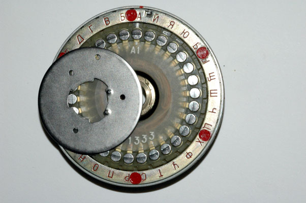
Adjusting the Multi-Adjustable Rotors:
The Ten multi-adjustable rotors can have their ring settings set to any one of
30 possible locations. They can also have their removable modular wiring
mazes set to any one of 60 possible locations. These settings are explained
below:
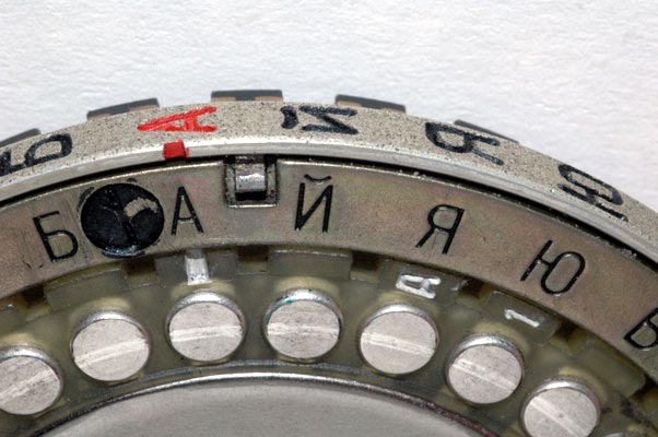
Ring Settings:
The outer ring has 30 Cyrillic letters and any one of these letters may be set
across from the index mark by pushing a spring-loaded locking pin inwards as
shown below:
In this picture, the Cyrillic letter "A" has been set to the index mark
which, as you will see from the next photograph, is also the outer ring
setting letter "A". When the outer ring is set to this position, it is said
to be in the BASE ring setting position.
This is a closer view of the BASE ring setting in which the outer letter
"A" is set across from the inner letter "A".

This is a view of the spring loaded locking pin on a different rotor.
Again, the outer ring has been set to the BASE ring setting in which the outer
letter "A" is set across from the inner letter "A".
Setting the removable modular wiring mazes:
The 30 wired connections between the 30 input contacts and the 30 output
contacts are made by a modular removable wiring maze. The modular wiring maze
is removed from the rotor by following the steps shown in the next
photographs: First, the retaining disc is rotated until it is released from
the brass central shaft:

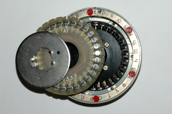
The removable modular wiring maze is removed by first releasing this metal
disc by rotating it so that it is no longer retained by the central brass
cylinder:
In this photograph, the retaining disc has been released from the brass
cylinder.
In this photograph, the retaining disc has been moved aside to reveal the
modular wiring maze. Note that the maze has a Cyrillic letter and a number.
The Cyrillic letters on the mazes correspond to the letters of the 10 rotors
BUT, ANY MAZE may be inserted into ANY of the 10 rotors. You are looking at
side 1 of the modular wiring maze "A". It can be flipped upside down to
reveal side 2. Please also note that the modular wiring maze has a white line
index mark that is pointing to the Cyrillic letter "A". WHEN THE INDEX MARK
ON SIDE 1 OF THE MODULAR WIRING MAZE IS FACING OUTWARDS AND POINTING TO THE
CYRILLIC LETTER "A", THE WIRING MAZE IS IN THE "BASE" POSITION. When the maze
AND the ring setting are in the BASE position, the rotor is in the OVERALL
BASE SETTING and it exactly corresponds to the like-lettered non-adjustable
rotor.
In this photograph, the modular wiring maze has been removed from the
rotor.
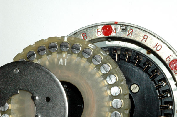
This is a close view of the index mark on the modular wiring maze. The
maze is oriented so that side 1 is facing outwards. The large figures "A1"
show that you are looking at side 1 of modular wiring maze "A". The small
figures A 1 printed around the outside of the modular wiring maze are put in
that position to allow the letter and number of the maze to be read even when
the metal disc holding the modular wiring maze is locked in place.
In this photograph, the index mark of the modular wiring maze has been set
to the Cyrillic letter "B" position.
In the following photograph, the modular wiring maze has been removed from
rotor "K" and flipped upside down so that side 2 is facing outwards. The
index mark on the modular wiring maze is pointing to the Cyrillic letter "A".
NOTE: This is the setting of adjustable rotor "K" that is shown in the wiring
table in the column on the far right. The heading of this column is: REVERSED
K. This means that multi-adjustable rotor "K" has had its internal modular
"K" wiring maze flipped to the position shown in this photograph. This
special wiring data set in the right column is shown to try to help clarify
what happens to the wired relationship between the 30 input contacts and 30
output contacts when the removable modular wiring maze is reversed in the way
shown in this photograph. Of course, there are a total of 60 possible
orientations of the removable modular wiring maze within the rotor but it is
hoped that showing the data for this one orientation will help researchers
extrapolate all of the other possibilities from this known wiring.
 This photograph shows rotor "K" with its removable modular wiring maze FLIPPED
OVER OR REVERSED so that side "2" of the maze is facing outward and its index
mark is pointing to the letter "A" position. THIS IS THE SETTING OF ROTOR "K"
THAT IS REFERRED TO AS "REVERSED K" IN THE COLUMN ON THE RIGHT SIDE OF THE
ROTOR WIRING TABLE. The wiring data shown in the right column of the table
show the connections between the input contacts and the output contacts when
the modular wiring maze is reversed in rotor "K" so that it is in this
position.
This photograph shows rotor "K" with its removable modular wiring maze FLIPPED
OVER OR REVERSED so that side "2" of the maze is facing outward and its index
mark is pointing to the letter "A" position. THIS IS THE SETTING OF ROTOR "K"
THAT IS REFERRED TO AS "REVERSED K" IN THE COLUMN ON THE RIGHT SIDE OF THE
ROTOR WIRING TABLE. The wiring data shown in the right column of the table
show the connections between the input contacts and the output contacts when
the modular wiring maze is reversed in rotor "K" so that it is in this
position.
It is important to remember that the wiring mazes from one rotor can be
removed and reinserted into any other rotor in 60 different orientations.
Please notice that the modular wiring maze has both an index mark and a
Cyrillic letter and a number 1 or 2. The modular wiring maze can be inserted
into a rotor with the index mark pointing to any of the 30 Cyrillic letter-
identified locations around the rotor. The modular wiring maze can be
inserted into the rotor with either side 1 or side 2 facing up. The "BASE"
positioning of a modular wiring maze is when the index mark points to the
Cyrillic letter "A" and side 1 is facing outward.
In addition to the 60 possible insertion positions of the modular wiring
maze, remember that these multi-adjustable rotors can also have their outer
Cyrillic letter ring rotated to any of 30 positions. When letter "A" on the
outer ring is adjacent to letter "A" on the rotor, the rotor is set to the
BASE ring setting.
Specific Wiring Data for all Multi-Adjustable Rotors:
When the Multi-Adjustable rotor is set to the base position with the modular
wiring maze index pointed to the Cyrillic letter "A" and side 1 facing out
AND when the outer letter ring is set so that the Cyrillic letter "A" on the
outer ring is adjacent to the Cyrillic letter "A" on the output face of the
rotor, the rotor is in its OVERALL "BASE" position.
The exact wiring between the 30 input and 30 output connections for the 10
multi-adjustable rotors set to the OVERALL BASE position is identical to the
wiring of the non-adjustable rotors and it is shown in the previous wiring
data table. This table shows the Cyrillic and the corresponding numerical
identifier for each of the 30 INPUT contacts in a column on the left side of
the table. The OUTPUT contact that is wired to each of the input contacts is
given by the number in the table under the Cyrillic letter identifying each of
the 10 rotors. To convert this number back into its corresponding Cyrillic
letter, just use the column on the left.
Redundant Note: The table applies to both the Non-Adjustable rotor set and
the Multi-Adjustable rotor set AS LONG AS THE MULTI-ADJUSTABLE ROTORS ARE SET
TO THE BASE POSITION. One final column is presented in the table to show the
internal wiring of multi-adjustable rotor "K" when the rotor ring setting is
first set to the base position and then the modular wiring maze is flipped
upside-down so that side "2" is facing out and the index mark is adjacent to
the Cyrillic Letter "A". With this wiring data it is possible to determine by
extrapolation, the exact internal wiring data for the multi-adjustable rotors
for any of the 60 possible insertion positions of the modular wiring maze.
Rotor Rotation Advance Blocking Pins:
The actual rotation of the rotors is controlled by the placement of the metal
pins adjacent to each of the contacts. These pins block or lock-out the drive
mechanism and determine which rotors will not rotate. This photograph shows
several of the pins and several of the un-pinned locations. A detailed table
of the locations of all of the pins in all of the rotors may be found
above.
Although all known Fialka rotors have exactly the same rotor advance blocking
pin placements it is possible, with a considerable amount of effort, to
change the placements. These pins can be removed from the rotors and inserted
into other holes but it is quite difficult to do this. It does not appear
to be a real adjustment of the rotor but rather an assembly convenience and
perhaps a provision for a major engineering revision. To remove the pins, the
6 screws holding the outer ring plate must be unscrewed. Each screw is
covered with red paint that both makes it difficult to unscrew, and also
reveals any attempts to do so. After the outer ring plate is removed, the
pins drop out of their cylindrical holes and can be repositioned. This is so
difficult and complex that for field and operational use, it can safely be
assumed that these pins are always to be found in the positions shown in
the table.
This is a close view of the rotation advance blocking pins for multi-
adjustable rotor "A".
Sample Rotor Rotation Data:
Sample rotation data for all 10 rotors for the first 20 letters typed into the
Fialka are shown in a table above.
Descriptions, Photographs and partial disassembly:
The following section describes and displays the Fialka 24 Volt Power Supply
and cables. This section is followed by, or linked to descriptions and
photographs of the Model M-125-MN and Model M-125-3MN Fialkas, and the metal
cover and accessories including a different rotor set.
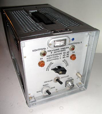
The front of the Fialka 24 volt DC power supply.
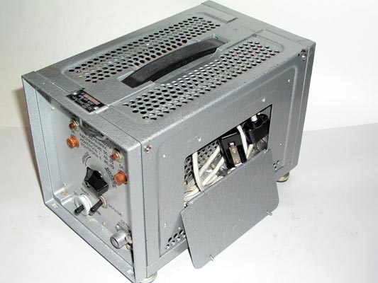
The right side of the Fialka 24 volt DC power supply showing the
compartment for storing the cables that connect the Fialka to the power
supply.
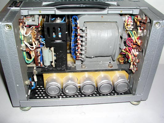
The right side of the Fialka 24 volt DC power supply after the cover is
removed. The power transformer and filter condensers are visible.
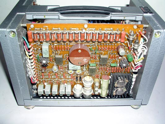
The left side of the Fialka 24 volt DC power supply after the cover is
removed. The voltage regulating circuitry is visible.
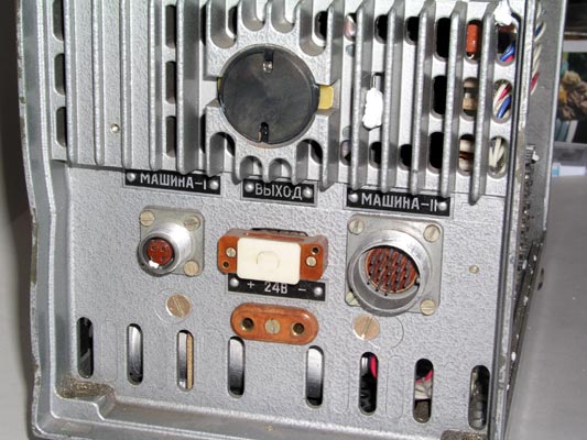
A close view of the back of the Fialka 24 volt DC power supply showing the
cable connectors.
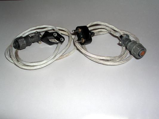
Two of the cables that connect the Fialka to its 24 volt power supply.
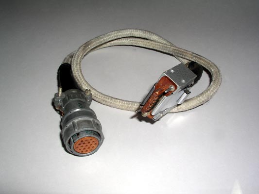
A third cable that connects the Fialka to its 24 volt power supply.
Descriptions, and Photographs:
The following section describes and displays the metal cover for the Fialka
and a set of accessories that may accompany the machine. This section is
followed by, or linked to descriptions and photographs of the 24 Volt Power
Supply and cables, and the Model M-125-MN and Model M-125-3MN Fialkas.
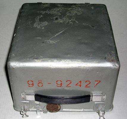
A metal cover protects the Fialka from damage in transit and contains a
variable number of accessories.
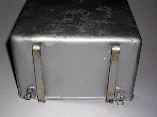
The back of the cover has two metal skids that hold it up.
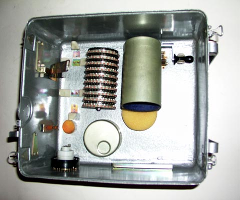
The inside of the cover may contain accessories as shown. These
accessories may include a hand crank, a spacer, additional print wheels, and a
different set of rotors.
This is the hand crank that may be found inside the cover.
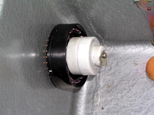
The additional print wheels, if included, are stored inside protective
white plastic covers and stacked on a shaft along with a spacer that allows a
reduced number of rotors to be installed on the shaft.
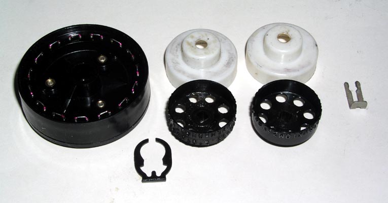
The additional print wheels are shown along with the
retaining clips and spacer after their protective white covers have been
removed.
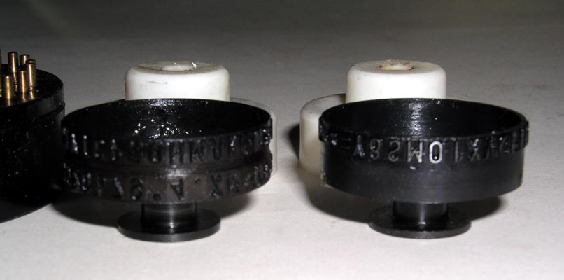
This is a closer view of the additional print wheels.
An additional set of rotors may be provided. This rotor set may be a
duplicate of the Brown, Non-Adjustable rotors or a set of the Black Multi-
Adjustable Modular Wiring Matrix rotors:
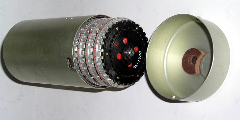
The additional set of rotors, if present, is stored in a protective metal
case.
The Brown, Non-Adjustable rotor set has already been shown and described
above and in the special detailed page explaining the rotors.
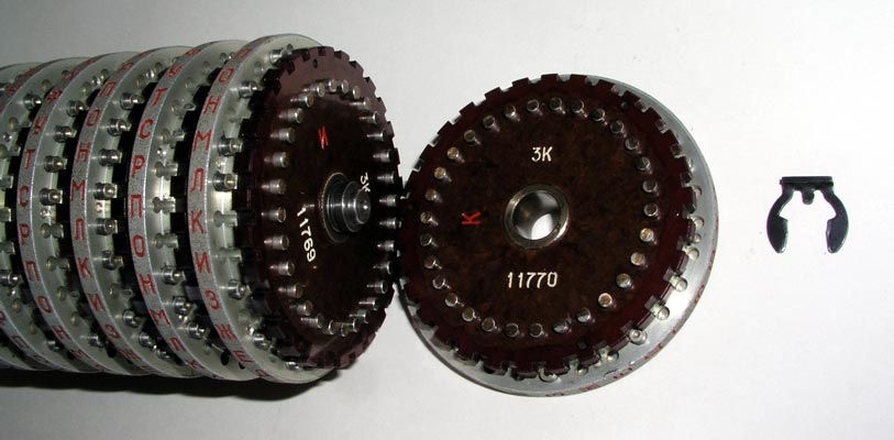
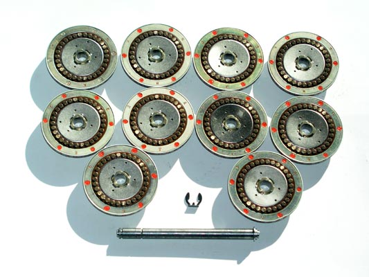
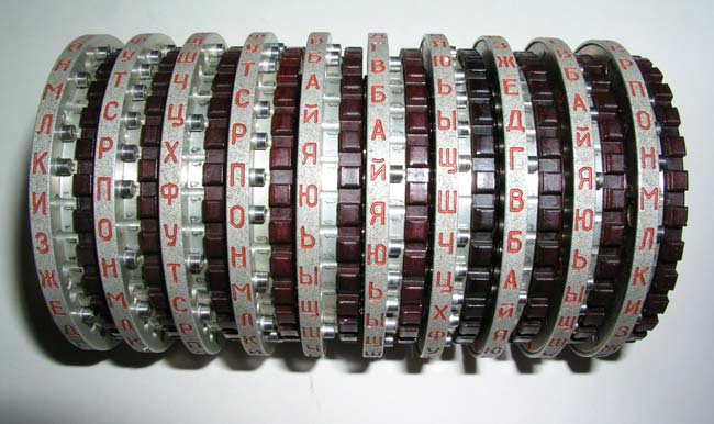
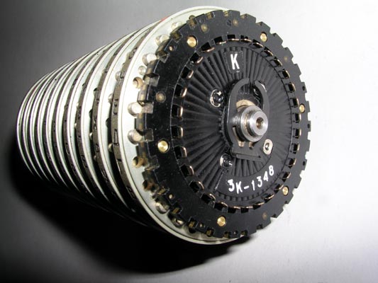
This is the special set of Black Multi-Adjustable Modular Wiring Maze rotors.
The retaining clip that holds the rotors on the shaft is also shown.
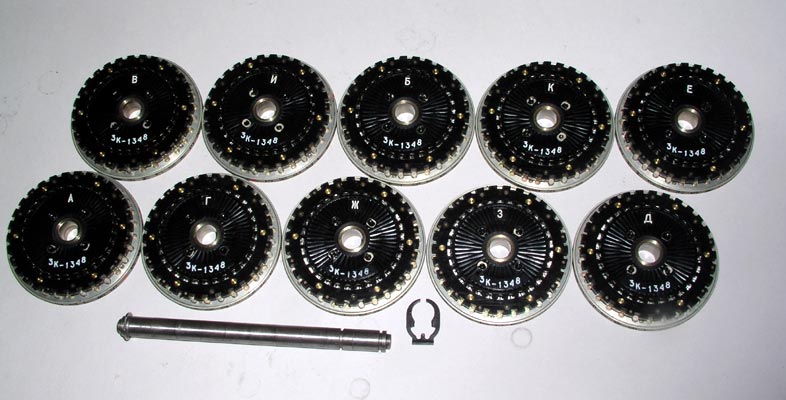
The input contact side of all 10 Black Multi-Adjustable Modular Wiring Maze
rotors after they have been removed from the shaft.

This photograph shows the special retaining clip location that allows 8 of
the rotors to be mounted on the shaft instead of 10. An accessory spacer
fills in the rest of the rotor stack width.
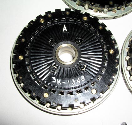
A close view of the input contacts on one of the 10 Black Multi-Adjustable
Modular Wiring Maze rotors.
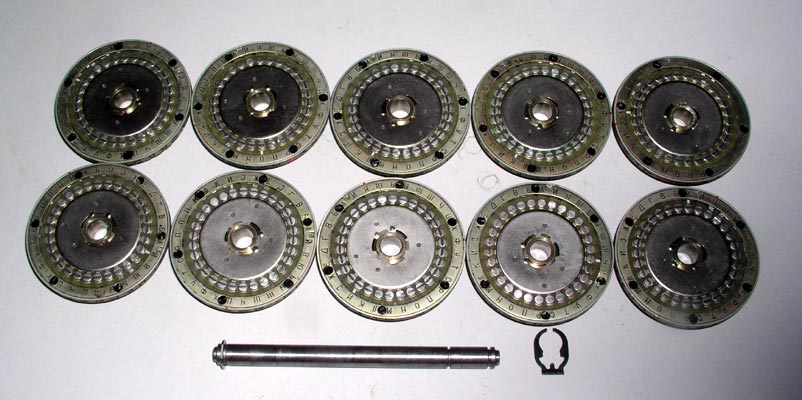
The output contact side of all 10 Black Multi-Adjustable Modular Wiring
Maze rotors after they have been removed from the shaft.
The output contacts on one of the 10 Black Multi-Adjustable
Modular Wiring Maze rotors.
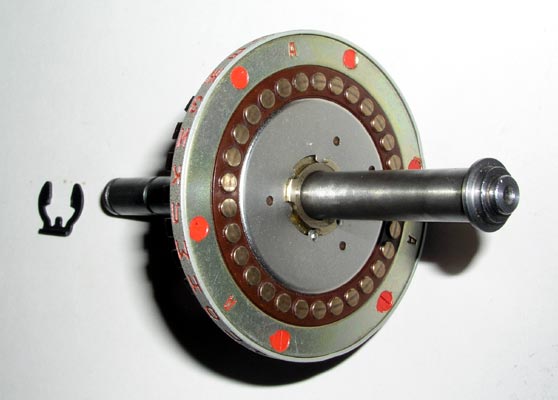
The adjustable outer ring setting on one of the 10 Black Multi-Adjustable
Modular Wiring Maze rotors. Pushing the pin inwards allows the outer ring to
be rotated to any of the 30 positions.
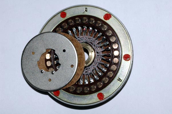
The removable reversible wiring maze module is shown being removed from one
of the 10 Black Multi-Adjustable Modular Wiring Maze rotors. It is removed by
releasing the metal retaining disc. Much more information on rotors, rotor
movement, and the exact internal wiring data is given in: this special rotor description and data page:
NOTE: I AM ALWAYS INTERESTED IN PHOTOGRAPHING OR BUYING VERY UNUSUAL ENIGMA-RELATED MATERIALS, PARTS, EARLY COMPUTERS, AND TELEGRAPH KEYS !
Professor Thomas B. Perera
Montclair State University
COPYRIGHT NOTICE: (Copyright (c) 2005: Prof. Tom Perera Ph. D.)
Although all the pictures and text are copyrighted, you may use any of them
for your own personal applications including public lectures and
demonstrations, publications and websites as long as you mention the
www.w1tp.com/enigma Museum. If you plan to offer them for sale to the public
in any form, you must email me for permission which I will generally grant as
long as you mention my museum: http://w1tp.com/enigma. My email address is
given at the bottom of this page. Some of the material may require contacting
other copyright owners for commercial use and I will inform you by email.
Please also see the disclaimer of warranty.