- Click BACK to Return to Previous Page:
The Enigma cipher machine consists of a battery and a series of keys and
switches which determine which of the 26 light bulbs will illuminate one of
the 26 letters of the alphabet.
If you type the word ''HELLO'' on the keyboard (the plaintext message),
letters ''AZRWK'' (the ciphertext message) may be illuminated by the
light bulbs. The ciphertext message ''AZRWK'' is then sent by telephone or
radio to a receiving station and there an operator types ''AZRWK'' into
another Enigma machine which illuminates light bulbs ''HELLO'' (The original
plaintext message).
In order for this to work, the Receiving Enigma machine must be set to the
same STARTING POSITION as the Sending Enigma Machine was set to. Since there
are heptillions of possible starting positions, even if an enemy has an Enigma
machine, it is virtually impossible for them to decode the ciphertext since
they would not know the proper STARTING POSITION.
Here is how the initial starting position is set before sending the first
message of the day:
SETTING UP THE DAY'S STARTING POSITION:
1. Set the Sequence of Rotors ( Code Wheels ) on the rotor shaft.
(Set the Position of the 3 Numbered Rotors or Code Wheels from left to right
on the rotor shaft.)
(Any three of the 5 numbered rotors can be placed in any of the three
positions on the shaft.)
There are therefore 60 possible sequences of three rotors.
2. Set the Number or Letter Rings on each of the 3 Rotors (Code Wheels).
(Set the 'Ring Setting' of each Rotor or 'Code Wheel'.)
There are 26 possible settings on each of the three rotors.
This gives 26 to the third power = (17,576) possible settings.
3. Set the Number or Letter to be visible through the 3 windows at the
start of coding.
(Set the 'Starting Positions' or 'Ground Setting' of the three Rotors.)
There are 26 possible settings in each of the three windows.
This gives 26 to the third power = (17,576) possible settings.
4. Insert Double-Plug Cables into the Plugboard (Patch Panel).
(Set the Plug-in wire Connections on Plugboard.)
There are anywhere from 0 to 13 plug wires which can be inserted into any of
the 26 sockets.
This gives: Sum from p=0 to 13 of 26!/(26-2p)! x p! x 2 to the p power
= (532,985,208,200,576) possible settings.
Combining these possibilities give us a total of
26,672,901,348,424,004,787,290,112 or about 10 to the 26 power possibile
starting settings. (Other ways of calculating this figure produce different
totals.)
ENIGMA MACHINE WIRING DIAGRAM:
(Trace the battery voltage through the keyboard letter 'Q', the
plugboard, the rotors, the plugboard again, the keyboard again,
and ultimately to the light bulb letter 'W').
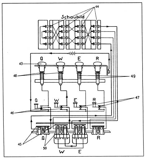 Wiring Diagram of the German Army Enigma Cipher Machine:
(Clockwise from top:)
(44) Rotor Contacts
(49) Lamp Contact Springs
(47) Key Contacts N. C.
(50) Jacks in Patch Panel
(45) Bypass Contacts for Unused Jack Panel Sockets
(46) Key Contacts N. O.
(48) Lamp Contacts
(43) Light Bulbs
ENIGMA MACHINE ROTOR DIAGRAM:
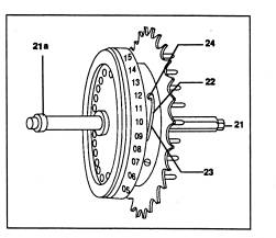
Enigma Rotors (Coding Cylinders)
(21a) Axle Shaft Collar
(24) Spring Stud for adjusting ring settings
(22) Retainer Spring for adjusting ring settings
(21) Axle Shaft
(23) Retainer Spring Button for adjusting ring settings
- Click BACK to Return to Previous Page:
Professor Thomas B. Perera
Montclair State University
- Email Address:
(To help me avoid automated 'junk mail' programs,
I ask you to type my email address as follows with no spaces between words:) - PLEASE TYPE: enigma
- THEN TYPE THE @ SYMBOL
- THEN TYPE: w1tp.com
- Please NOTE: It is w(the figure 1)tp.com not wLtp or wItp.
- Please NOTE: You MUST include the word ENIGMA in the email Subject Line.
- ( Please Inquire Before Sending Attachments Larger Than 100KB ! )
http://w1tp.com
or: http://www.chss.montclair.edu/~pererat/telegrap.htm
Internet On-Line ENIGMA Museum: http://w1tp.com/enigma